Handwired Iris Keyboard Build
Forever in search of the best keyboard, I recently embarked on the journey of hand wiring a keyboard. I had been using a Hot Dox keyboard for the better part of the last year and liked it for the most part. The Ergodox layout had two main issues for my uses:
- It was large and had too many keys
- the thumb cluster wasn’t within easy reach for me
I only ever used the two “2u” sized thumb keys so the rest of the thumb cluster just served to get in the way. The keys on the inside-most column of the 5x7 layout were nice to use sometimes (I had them mapped to brackets and parentheses) but they were a decent stretch so I didn’t use them often.
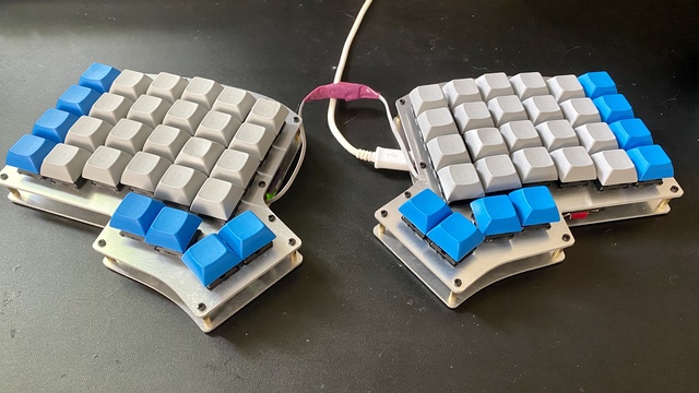
I discovered the plates for an Iris Keyboard when rummaging through some spare keyboard parts. The Iris is also a split, ortholinear keyboard like the Hot Dox and Ergodox but has a 4x6 grid with only 4 thumb keys. The resulting desk footprint of the Iris is considerably smaller than the Ergodox while still remaining fully functional. In my opinion, the thumb cluster is more ergonomically designed and actually allows for all four of the keys to be used rather than just two on the Ergodox.
The major hurdle for me was the extreme DIY nature of hand wiring the keyboard. The Hot Dox was incredibly easy to build by comparison, I didn’t have to break out the soldering iron once for that kit. That being said, building the Iris gave me a much better understanding of how the keyboard and QMK work. Overall I would recommend the experience but it’s definitely not trivial.
The Build
I found that I needed the following materials to build the Iris:
- Top and Bottom plates for each side (part of the kit)
- Standoffs + screws for attaching the plates (part of the kit)
- 56 switches, I used Cherry MX Silent Reds for the grid and Cherry MX Clears for the thumb clusters
- 56 diodes, any can do but 1N4148s are cheap and easy to find
- 2 Pro Micro microcontrollers, one for each side
- Some ribbon cables
- Some thicker (22 AWG or so) wire
- 2 SPST switches
- Ideally some sort of 4 wire cable and 2 connectors, but I didn’t use that. More on that later.
Assembling the Matrix
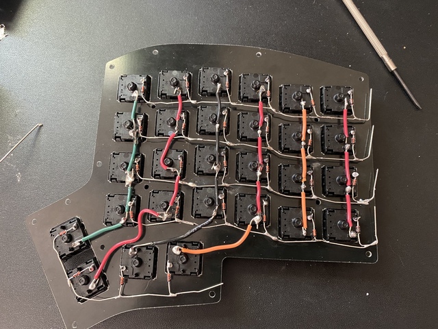
A keyboard tells the computer which key was pressed by sending a logic state “0” on the pins that correspond to its position. This requires two electrical characteristics – pressing the switch must close a circuit to send a “0” instead of “1” like it would normally and there must be some way to locate what switch was pressed. We identify the key’s location by creating a “matrix” where each key lies on a column and a row. Each key in a given column is wired together and each key on a given row is wired together.
Each key needs its own diode connected to its row to ensure that other key presses don’t interfere with this key’s ability to send its location. The writeup on Komar’s Techblog goes more into detail about how this matrix design allows for n-key rollover, or NKRO.
I used the approach where the legs of the diode for the row wiring and found it to be good solution. The diode legs are not insulated so I used insulating wires for the rest of the build to ensure that I would not short out anything.
Matrix, Meet Micro
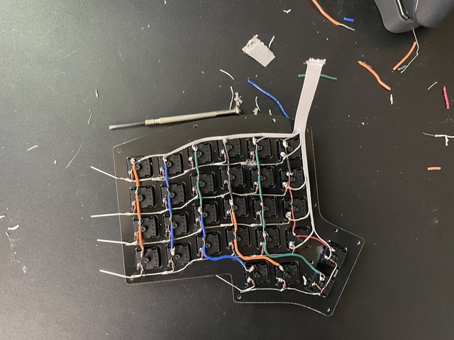
Once the matrix is wired up, each row and each column need connected to a GPIO pin on the microcontroller. I used Pro Micro controllers for each side of the keyboard. It is possible to avoid using two micros with some complicated wiring but I found that it was much easier to use a dedicated micro for each side.
The ribbon cable made this step much cleaner than it would have been with the thicker wire I used for the matrix. In addition to easily organizing the cable on the edge of the keys the ribbon cable folded over on itself very nicely when attaching the bottom plate. The Iris is not a very thick keyboard so there was not much additional depth left between the micro and the switches.
Important Note
I made a mistake on this step of the wiring on my first attempt. It is quite convenient to use the legs of the switches as a joint where wires will connect and be soldered together, but this does not work for the row connections. I had originally soldered my row connections to the row-side leg of one of the switches, but that prevented the other keys on the row from sending presses. This is because the key’s diode was preventing current from flowing from the other switches to the row connection. I moved the solder joint for the row connections to one of the diode legs and everything worked nicely.
Bridging the Gap
The two sides each have their own microcontroller so they can work on their own
but we need them to talk to the computer through just one side. The two sides can
either use “soft serial” comms over three wires to talk to each other or they
can talk over I2C with four wires.
I had a TRRS cable and associated
jacks sitting around so I opted to use I2C over its four wires. The jacks that I
had were incredibly snug fitting on the cable though, and I ended up with a whole
bunch of issues getting a connection between the two sides. The TRRS cable seems
like a better option in general compared to alternatives like an RJ45 cable or
similar but my hardware was not so great.
After dealing with issues with my TRRS setup for a few hours I decided to cut my losses and solder the wires for the two sides together. This is certainly not the most reliable or prettiest option but it was an easy option for the time. I’m planning to order some more TRRS jacks and another cable in the future so I can transport the two sides individually if I need to and make the board look less like a skunkworks project.
Reset Switch
I forgot about this until I went to flash some firmware onto the board; I’d
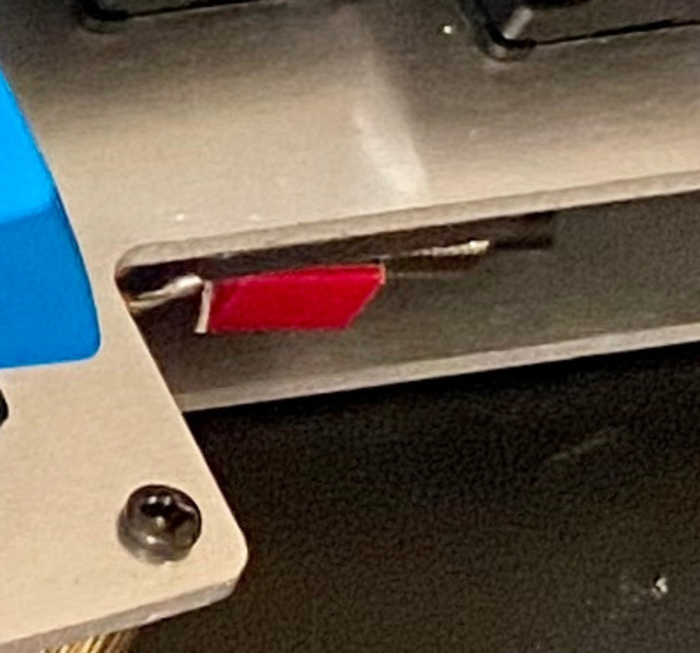
recommend taking care of this with the rest of the wiring. I used a momentary
SPST switch from my old college EE lab kit for each side. One leg gets a connection
to GND and one of the other two legs gets a connection to RST on the Pro Micro.
I had to play with the wiring a bit to figure out which of the legs was the normally
open connection and which one was normally closed to ensure that the reset only
occurs when the switch is pressed.
After wiring it up I used a piece of double sided adhesive foam to attach it to the top plate near the thumb cluster. You can see a bit of it in the header photo for this article.
QMK Config
I loved the customization possibilities with QMK on my Hot Dox and it was the clear choice for my Iris build. The Iris is already supported by QMK but the configuration is intended for an Iris that uses a PCB rather than a hand-wired clone like mine. I forked QMK on github and started making my own modified version of the Iris QMK configuration.
Describing the Wiring
The first step to getting the Iris up and running was defining the wiring in the QMK config header. I chose the pins that made the most sense for the geometry of my handwired build but that, unsurprisingly, did not match the pins used on the PCB version of the Iris.
One source of confusion for me in this step was the fact that each pin on the Pro Micro has a multitude of names. The identifiers used by QMK are the Arduino pin names rather than the names shown on the physical board or its wiring diagram. These names are copied below. The top of the diagram is where the micro-USB connector lies on the board.
 Pro Micro Pinout:

     D3 +--------+ RAW
     D2 | +----+ | GND
     GND|        | RST
     GND|        | VCC
SDA  D1 |        | F4
SCL  D0 |        | F5
     D4 |        | F6
     C6 |        | F7
     D7 |        | B1
     E6 |        | B3
     B4 |        | B2
     B5 +--------+ B6
With this in mind, I copied the files from qmk_firmware/keyboards/keebio/iris/rev4
(the latest keyboard revision at the time of writing) to a new folder in the same
parent directory that I called “Handwire”. I changed these files to match my keyboard’s
wiring and set this layout as my keyboard type with the QMK CLI.
The pins for the matrix wiring are defined with the following lines in config.h:
#define MATRIX_ROW_PINS        { B1, F7, F6, F5, F4 }
#define MATRIX_COL_PINS        { B3, B2, B6, E6, B4, B5 }
The row pins are ordered from the top (furthest from the wrist) down and the column pins are ordered from the inside (thumb side) out for the two sides.
Split Keyboard Things
Most of the split keyboard-specific QMK configuration details were handled already
by the Iris files that I reused, but there were two items that I had to define
in my keymap. This involved a different config.h file than the previously
mentioned wiring config, this file was in a keymap directory that I created rather
than in the “Handwire” layout config.
I defined the following two macros in keymaps/<MY_USER_NAME>/config.h:
USE_I2CMASTER_RIGHT
These macros tell QMK that I am using I2C over four wires to communicate between the sides of the keyboard and that I will always plug the keyboard in to my computer by way of the micro on the right hand side. There are other configuration options available for determining the master side but I found that it was easiest to just stick with the right side permanently.
Keymap
I was able to transfer my Hot Dox keyboard layout without a ton of modifications
because I was pretty much only using 56 keys on the Hot Dox anyways. The top row
was where I most noticed the more cramped layout of the Iris but I was able to
resolve that issue with the KC_GESC key macro in QMK. This allows me wrap the
grave key and the escape key into one all on the same layer. I then rearranged
the number row a bit so that it is in order from 0-9 rather than 1-9 followed by 0.
This kept the numbers, and more importantly, their symbols, in the same position
that I was used to on the Hot Dox.
You can view my current keymap for my Iris board in my fork of QMK.